

FAKTA TERMOGRAFI
Fakta om termografi
Grunderna i termografi och emissionsfaktor (och hur du ställer in den), faktorer som påverkar mätningar, tips vid termografering utomhus och en emissionsfaktortabell.
Termografi i teorin.
Alla objekt med en temperatur över den absoluta nollpunkten (0 Kelvin = -273,15 °C) avger IR-strålning. Det mänskliga ögat uppfattar inte sådan strålning, eftersom vi i stort sett är blinda för denna våglängd. Det är däremot inte värmekameran. Den kritiska komponenten – detektorn – är känslig för IR-strålning. Genom att mäta IR-strålningens styrka avgör den temperaturen på mätobjektets yta och gör den synlig för det mänskliga ögat med hjälp av en värmebild. Denna process kallas för termografi.
För att göra IR-strålningen synlig registreras den av detektorn och omvandlas till en elektrisk signal. Därefter får varje signal en viss färg, som sedan visas på värmekamerans display. I princip översätter alltså värmekameran våglängder från det infraröda spektrat till våglängder som är synliga för det mänskliga ögat (färger).

Det finns en vanlig missuppfattning om att det går att se inuti föremål med en värmekamera. Det går alltså inte, det är enbart yttemperaturen som kan visualiseras.
Emission, reflektion och transmission.
IR-strålningen som registreras med en värmekamera består av emission, transmission och reflektion.
Emission (ε)
Emission är förmågan hos ett material att avge IR-strålning. Denna förmåga uttrycks med hjälp av emissionsfaktorn. Den beror bland annat på själva materialet och på ytstrukturen. Exempelvis har solen en emissionsfaktor på 100%. Detta värde uppträder ingen annanstans. Betong ligger å andra sidan nära med en emissionsfaktor på 93%. Det innebär att 93% av IR-strålningen avges från själva betongen.
Reflektion (ρ)
Resterande 7% är reflektioner från materialet / mätobjektet, dvs. temperaturen som reflekteras från mätobjektet. I en värmekamera går det att ange emissionsfaktor och reflekterad temperatur, för att erhålla en värmebild med så hög precision som möjligt.
Transmission (t)
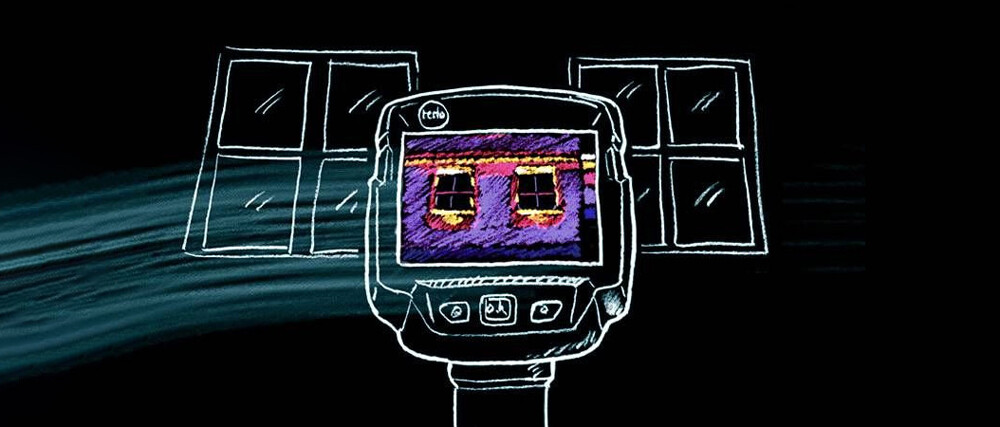
Transmission är förmågan hos ett material att låta IR-strålning passera igenom det (transmissivitet). Det som verkar genomskinligt för ögat är det inte alltid för IR-strålningen. Exempelvis är fönsterglas nästan helt ogenomskinligt för IR-strålning medan vissa tunna plastmaterial som är helt ogenomskinliga för ögat kan vara nästan helt genomskinliga för IR-strålningen. De flesta material släpper dock inte igenom IR-strålning, vilket innebär att som regel är transmissiviteten nästan noll i de flesta fall och kan alltså ignoreras.

Sambandet mellan emission och reflektion
1. Mätobjekt med hög emissionsfaktor (ε ≥ 0,8):
- Har låg reflektans (ρ): ρ = 1 – ε
- Temperaturen på sådana objekt kan mycket enkelt mätas med en värmekamera
2. Mätobjekt med medelhög emissionsfaktor (0,8 < ε < 0,6):
- Har medelhög reflektans (ρ): ρ = 1 – ε
- Temperaturen på sådana objekt kan enkelt mätas med en värmekamera
3. Mätobjekt med låg emissionsfaktor (ε ≤ 0,6)
- Har hög reflektans (ρ): ρ = 1 – ε
- Det går att använda värmekameran för att mäta temperaturen, men du bör granska mätresultaten mycket omsorgsfullt och vara noggrann med att rätt emissionsfaktor används.
Inställning av emissionsfaktor.
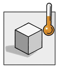
Att kontrollera att emissionsfaktorn är rätt inställd är särskilt viktigt när det är stor temperaturskillnad mellan mätobjektet och omgivningen.
När temperaturen hos mätobjektet är högre än omgivningstemperaturen:
- En för högt inställd emissionsfaktor resulterar i för låga temperaturer i värmebilden
- En för lågt inställd emissionsfaktor resulterar i för höga temperaturer i värmebilden
När temperaturen hos mätobjektet är lägre än omgivningstemperaturen
- En för högt inställd emissionsfaktor resulterar i för höga temperaturer i värmebilden
- En för lågt inställd emissionsfaktor resulterar i för låga temperaturer i värmebilden
Tips om emissionsfaktorn.
- Ju större skillnaden är mellan mätobjektets och omgivningens temperatur och ju lägre emissionsfaktorn är, desto större blir mätfelen. Dessa fel blir ännu större om emissionsfaktorn är felaktigt inställd.
- Många material som är genomskinliga för det mänskliga ögat (som glas) är inte genomträngliga för IR-strålning.
- Bland det fåtal transmissiva material som finns hittar vi exempelvis tunna plastmaterial och germanium, materialet som linsen och skyddsglaset är tillverkat av i en värmekamera från Testo.
- Ta vid behov bort allt som täcker mätobjektet, annars kommer värmekameran enbart att mäta yttemperaturen på täckmaterialet.
- Ta alltid hänsyn till mätobjektets driftsförhållanden
- Om delar under ytan påverkar temperaturfördelningen på mätobjektets yta genom värmeledning, kan man ofta identifiera invändiga strukturer i värmebilden. Det är ändå så att värmekameran aldrig mäter något annat än yttemperaturer. Det går alltså inte att dra några slutsatser om temperaturvärden inuti mätobjektet.
Synfält, minsta mätbara objekt och mätfläck.
Tips om emissionsfaktorn
Synfältet (FOV) beskriver det område som är synligt för värmekameran. Den beror på vilken optik som används. Vidvinkelobjektiv är lämpliga för stora synfält, teleobjektiv för god rumsupplösning. Ju större synfält desto mer ser du. Ett brett synfält (> 30°) är särskilt användbart inomhus, eftersom väggarna begränsar möjligheterna att stå längre ifrån mätobjektet med värmekameran, för att se mer.

Minsta mätbara objekt / mätfläck (IFOVmeas)
Det minsta mätbara objektet beskriver det minsta objekt som inte bara kan identifieras, utan vars temperatur kan mätas med precision. Vid en rumsupplösning hos linsen på 3,5 mrad och ett mätavstånd på 1 m, har det minsta mätbara objektet en kantlängd på 3,5 mm och visas i displayen som en pixel. För en noggrann mätning bör mätobjektet vara 2 till 3 gånger högre än det minsta mätbara objektet. Som en tumregel gäller följande för det minsta mätbara objektet (IFOVmeas): IFOVmeas ≈ 3 x IFOVgeo.
Minsta identifierbara objekt (IFOVgeo)
Det minsta identifierbara objektet är det minsta mått som kan identifieras genom en pixel. En pixel är ett element på värmekamerans detektor som registrerar IR-strålning och omvandlar den till elektriska signaler. Varje pixel motsvarar ett mätvärde.

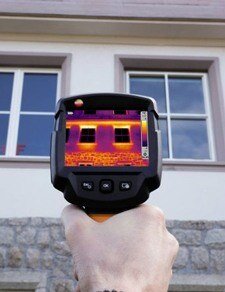
Termografi i praktiken.
Beröringsfri temperaturmätning med en värmekamera är oumbärlig i många tillämpningar. Om du följer några grundläggande regler kommer du att kunna använda infraröd mätning ännu mer effektivt från och med nu.
- Läs mer om de viktigaste teoretiska principerna för termografi
- Dra nytta av värdefulla tips för ditt dagliga arbete med en värmekamera.
Mätobjektet.
1. Material och emissionsfaktor
En värmekamera mäter den långvågiga IR-strålning som alla föremål avger. Mängden IR-strålning som mätobjektet avger beror på materialets yta.
OBS! Varje yta har en specifik emissionsfaktor.


2. Färg
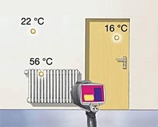
Ytans färg har ingen betydande effekt på den långvågiga IR-strålningen som mätobjektet avger. Den avgörande faktorn är temperaturen. Exempelvis avger ett svartlackerat värmeelement exakt samma mängd långvågig IR-strålning som ett vitlackerat med samma temperatur.
OBS! Ytans färg spelar nästan ingen roll.
3. Mätobjektets yta
Vid termografering spelar mätobjektets ytstruktur en avgörande roll. Ytans emissionsfaktor varierar beroende på ytstrukturen. Beläggningar och smuts spelar också roll.
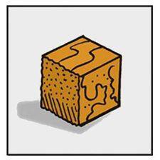
Ytstruktur
Som regel är emissionsfaktorn på släta, blanka, reflekterande och/eller polerade ytor något lägre än på ytor med struktur eller matta, grova, vittrade och/eller repiga ytor, även om materialet är detsamma.
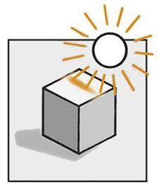
OBS! Vid mätning på släta ytor ska man vara särskilt uppmärksam på om det finns andra strålningskällor i omgivningen (t.ex. solljus, värmeelement etc).
Fukt, snö och frost på ytan
Vatten, snö och frost har relativt höga emissionsfaktorer (ca 0,85 < ε < 0,96). Därför är mätning på sådana ytor normalt inget problem. Däremot måste man komma ihåg att temperaturen på mätobjektet kan störas av naturliga beläggningar av denna typ. Det beror på att fukt kyler ned ytan på mätobjektet när den förångas och snö har goda isolerande egenskaper. Rimfrost bildar normalt ingen tät yta. Därför behöver man ta hänsyn till emissionsfaktorn för både rimfrosten och den underliggande ytan vid mätningar.
OBS! Undvik om möjligt att mäta på våta, snö- eller frosttäckta ytor.
Smuts och främmande föremål på ytan
Smuts och främmande föremål som t.ex. damm, sot eller smörjmedel på ytan höjer vanligtvis emissionsfaktorn. Därför är det oftast inget problem att mäta på smutsiga föremål. Värmekameran mäter emellertid alltid yttemperaturen, dvs. smutsen och inte den exakta temperaturen hos den underliggande ytan på mätobjektet.
OBS! Undvik att mäta på lös smuts (felmätning om luft inkluderas i materialet).
Mätomgivningen.
1. Omgivande temperatur
En annan faktor som du behöver ta hänsyn till är den reflekterade temperaturen (RTC) och emissionsfaktorns inställning (ε), så att din värmekamera kan beräkna yttemperaturen korrekt.
- I många fall är den reflekterade temperaturen identisk med den omgivande lufttemperaturen.
- Att kontrollera att emissionsfaktorn är rätt inställd är viktigt när det är stor temperaturskillnad mellan mätobjektet och omgivningen.
2. Strålnings- och störningskällor
Alla objekt med en temperatur över absolut noll (0 Kelvin = -273,15 °C) avger IR-strålning. Objekt vars temperatur skiljer sig mycket från mätobjektet kan störa IR-mätningen, på grund av sin egen strålning. Du bör undvika eller skärma av sådana störningskällor när det är möjligt.
- Använd exempelvis en skärm eller en wellpapp-kartong för att skärma av störningskällorna.
- Du kan mäta den reflekterade strålningen, t.ex. med hjälp av en Lambert-strålare, i kombination med din värmekamera.
3. Väder
Moln
Idealiskt ska IR-mätningar utomhus ske när molntäcket är tjockt. Anledning: Mätobjektet är avskärmat från solstrålning och ”kall himmelsstrålning”.
Nederbörd
Vatten, is och snö har hög emissionsfaktor och är ogenomtränglig för IR-strålning. Dessutom kan mätning på våta objekt resultera i mätfel, eftersom ytan på mätobjektet kyls ned när fukten förångas.
OBS! Kraftig nederbörd (regn, snö) kan störa mätresultatet.
4. Luft / Luftfuktighet
Om det finns kondens pga hög relativ luftfuktighet på värmekamerans optik (eller skyddsglas), kan IR-strålningen inte tas emot i sin helhet. På grund av vattnet når strålningen inte ända fram till optiken. Extremt tät dimma kan också påverka mätningen eftersom dropparna mellan kameran och mätobjektet släpper igenom mindre IR-strålning.
OBS! Kontrollera att den relativa luftfuktigheten i omgivningen är låg. Det ger dig möjlighet att undvika kondensation i luften (dimma), på mätobjektet, skyddsglaset eller värmekamerans lins.

Luftströmmar
Som ett resultat av värmeväxlingen (konvektionen) har luften nära ytan samma temperatur som mätobjektet. Om det är blåsigt eller dragigt kommer detta luftskikt att ”blåsa bort” och ersättas med ett nytt skikt som ännu inte anpassat sig till mätobjektets temperatur. Som ett resultat av konvektionen kommer värme att föras bort från ett varmt mätobjekt eller absorberas av ett kallt mätobjekt, tills lufttemperaturen och mätobjektets yta har anpassat sig till varandra. Den här värmeväxlingseffekten ökar ju större temperaturskillnaden är mellan mätobjektets yta och omgivningsluften.
OBS! Luftströmmar eller drag i rummet kan påverka temperaturmätningar med värmekameror.
Luftföroreningar
Vissa partiklar som t.ex. damm, sot och rök och även vissa ångor har hög emissionsfaktor och är knappt genomsläppliga. Det innebär att de kan störa mätningen, eftersom de avger sin egen IR-strålning som tas emot av värmekameran. Dessutom kan bara en del av IR-strålningen från mätobjektet ta sig ända fram till värmekameran, eftersom den sprids och absorberas av partiklarna i luften.
5. Ljus
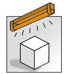
Ljus eller belysning har ingen avgörande betydelse på mätningar som görs med en värmekamera. Det går också att mäta i mörker, eftersom värmekameran mäter långvågig IR-strålning. Det finns emellertid ljuskällor som själva avger IR-värmestrålning och alltså kan påverka temperaturen i intilliggande objekt.
- Mät därför exempelvis inte i direkt solljus eller nära en varm glödlampa.
- Kalla ljuskällor som LED-lampor eller neonljus stör inte mätningarna nämnvärt: de omvandlar den större delen av energin till synligt ljus och inte till IR-strålning.
Att tänka på vid termografering utomhus.
IR-strålningen från en klar himmel kallas för ”kall himmelsstrålning”. En molnfri dag reflekteras kall himmelsstrålning (~ -50 … -60 °C) och varm solstrålning (~ 5500 °C). Solen tar bara upp en liten del av hela himlavalvet, vilket innebär att den reflekterade temperaturen normalt ligger under 0 °C, även en solig dag. Föremål värms upp av solen eftersom de absorberar solljus. Det har en stor inverkan på yttemperaturen – ibland flera timmar efter att ha utsatts för solstrålning.
Tips & Tricks för termografering utomhus
- Den idealiska tiden för termografering utomhus är under de tidiga morgontimmarna och/eller vid tät molnighet. Det bör inte regna eller snöa. Dimma och kraftig blåst är också bäst att undvika.
- Under mätningen är det bra att byta position för att kunna upptäcka reflektioner. Reflektioner förändras medan värmeavvikelser hos mätobjektet förblir desamma – även när siktvinkeln ändras.
- Undvik mätningar nära mycket varma eller kalla objekt, eller skärma av dem.
- Undvik direkt solljus, även om solen lyste flera timmar före mätningen. Ta hänsyn till molntäcken, även om de uppträdde flera timmar före mätningen.
- Mät inte om det finns kondens på värmekameran.
- Mät inte i starkt förorenad luft (t.ex. precis efter att damm har rörts upp).
Emissionsfaktor-tabell.
| Material | Materialtemperatur | Emissionsfaktor |
| Aluminium, blankvalsad | 170 °C | 0,04 |
| Aluminium, ej oxiderad | 25 °C | 0,02 |
| Aluminium , kraftigt oxiderad | 93 °C | 0,20 |
| Aluminium, högpolerad | 100 °C | 0,09 |
| Bomull | 20 °C | 0,77 |
| Betong | 25 °C | 0,93 |
| Bly, grovt | 40 °C | 0,43 |
| Bly, oxiderat | 40 °C | 0,43 |
| Krom | 40 °C | 0,08 |
| Krom, polerad | 150 °C | 0,06 |
| Is, slät | 0 °C | 0,97 |
| Järn, smärglat | 20 °C | 0,24 |
| Järn med gjutbeläggning | 100 °C | 0,80 |
| Järn med valsbeläggning | 20 °C | 0,77 |
| Gips | 20 °C | 0,90 |
| Glas | 90 °C | 0,94 |
| Granit | 20 °C | 0,45 |
| Gummi, hårt | 23 °C | 0,94 |
| Gummi, mjukt grått | 23 °C | 0,89 |
| Gjutjärn, oxiderat | 200 °C | 0,64 |
| Trä | 70 °C | 0,94 |
| Kork | 20 °C | 0,70 |
| Radiatorelement, svarteloxerat | 50 °C | 0,98 |
| Koppar, något matt | 20 °C | 0,04 |
| Koppar, oxiderad | 130 °C | 0,76 |
| Koppar, polerad | 40 °C | 0,03 |
| Koppar, valsad | 40 °C | 0,64 |
| Plast: PE, PP, PVC | 20 °C | 0,94 |
| Blå färg på aluminiumfolie | 40 °C | 0,78 |
| Mattsvart färg | 80 °C | 0,97 |
| Vit färg | 90 °C | 0,95 |
| Vit marmor | 40 °C | 0,95 |
| Murverk | 40 °C | 0,93 |
| Mässing, oxiderad | 200 °C | 0,61 |
| Oljefärg (alla färger) | 90 °C | 0,92 ... 0,96 |
| Papper | 20 °C | 0,97 |
| Porslin | 20 °C | 0,92 |
| Sandsten | 40 °C | 0,67 |
| Stål, värmebehandlad yta | 200 °C | 0,52 |
| Stål, oxiderat | 200 °C | 0,79 |
| Stål, kallvalsat | 93 °C | 0,75 ... 0,85 |
| Bränd lera | 70 °C | 0,91 |
| Transformatorfärg | 70 °C | 0,94 |
| Tegelsten, murbruk, puts | 20 °C | 0,93 |
| Zink, oxiderad | - | 0,1 |
Värmekameror och termografikurser från Nordtec.

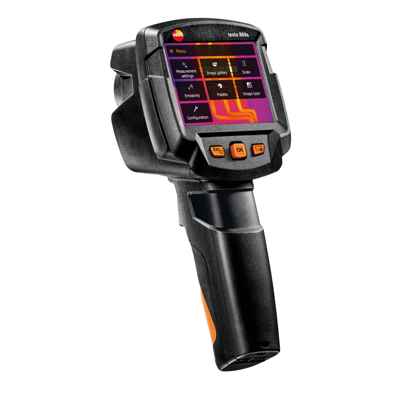
Instegsmodell testo 865s
Testo har ett brett program av duktiga och prisvärda värmekameror i olika klasser. Instegsmodellen 865s har en upplösning på 19 200 px.
Proffs- och expertklass
Mätseten i testo 890-serien har exceptionellt hög upplösning och hög termisk känslighet. De har dessutom ett flertal viktiga funktioner som röstinspelning utbytbara objektiv m.m.
Termografikurser
Nordtec har en grundkurs inom termografi som ingår vid köp av värmekamera. Kursen genomförs av en kvalificerad och erfaren kursledare som blandar teori och praktik för optimal inlärning.